



Hydro-Pro Heat Pump (Type 22T) exploded view & spare parts
 Certificat botiga en línia
 Devolucions fàcils dins 14 dies


Llista de recanvis

Hydro-Pro - Heat Pump LED On/Off Control Display Panel XK 001 V1 MM011 - 7010515
168,45 €

Hydro-Pro - Heat Pump WiFi LED On/Off Control Panel (Type WiFi12iMM011) - 7023601
302,95 €
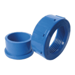
Hydro-Pro - Water Connection Set 50mm Glue Socket (Pack of 2) - 7014127
41,95 €

Pressure Gauge 0–55 Bar R410A - 7010518
47,45 €
Hydro-Pro - Water Connection Set 50mm Glue Socket (Pack of 2) - 7014127
41,95 €

Hydro-Pro - Titanium Heat Exchanger for Type 22 / 22T ABS Heat Pump - 7020788
925,45 €

Flotide/MEGA - Heat Pump Water Flow Switch with 32 mm Glue Adapter - 7006471
51,45 €
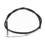
Flotide/MEGA - Water Outlet Temperature Sensor T2 - 7010535
10,45 €

Water Inlet Temperature Sensor T1 for Hydro-Pro Heat Pump - 7010534
10,45 €
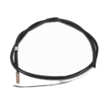
Pipe Temperature Sensor T3 - 7010533
12,45 €
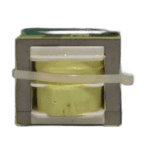
Hydro-Pro - Replacement PC Board ZK 102 V1 for Heat Pump Type 13 - 7010514
168,45 €

Flotide/MEGA - Heat Pump Transformer ZHL-03/EL-48 - 7010532
26,45 €
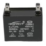
Hydro-Pro - Fan Motor Capacitor 6µF Square Type with Plug Connector - 7019180
9,95 €

Motor Terminal Block 380–400 V / 16 A - 7010526
6,45 €

Flotide/MEGA - Phase Sequence Relay for Heat Pump Type 12 - 7017965
103,45 €

Flotide/MEGA - Low Pressure Switch 0.1–0.3 MPa (Heat Pump A3/32) - 7024791
21,95 €

Flotide/MEGA - Heat Pump High Pressure Switch 3.6–4.2 MPa - 7024793
21,95 €
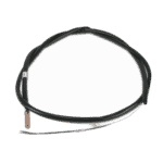
Hydro-Pro Heat Pump Ambient Temperature Sensor T5 - 7010537
10,45 €

Descripció
Hydro-Pro Heat Pump (Type 22T) exploded view & spare parts
This page provides the full exploded-view diagram and bill of materials for the Hydro-Pro Heat Pump Type 22T, carrying factory reference 7018528. The Type 22T is a vertical-format model in the Hydro-Pro swimming pool heat pump range, designed to heat in-ground and above-ground pools during an extended season and capable of operating down to −5 °C. As a three-phase unit, incorrect phase connection can cause the electric motors to run in reverse, which is why the diagram covers the electrical box and phase-protection components in detail. Use the numbered call-outs and the parts list below to pinpoint the exact component you need in just a few minutes, without having to page through a full service manual.
Com utilitzar el diagrama numerat per trobar la teva peça
Every number printed on the exploded-view diagram corresponds directly to a row in the parts table beneath it — locate the area of the unit where the fault or wear has occurred, read off the position number printed on the image, then find that same number in the list to reveal the part description and its SKU. Where a SKU is shown, that part is available to order directly from the table; positions without a SKU are structural or refrigerant-circuit items that are typically replaced at service-centre level rather than as field spares. Pay close attention to positions that carry a letter suffix: positions 10a, 10b, and 10c, for example, all occupy the same general location on the control panel but represent three distinct display variants — fitting the wrong one will leave the unit non-functional. Similarly, positions 54a i 54b sit side by side in the refrigerant circuit but are calibrated to entirely different pressure ranges, so they must not be swapped. Some position numbers — for instance 11 i 16, which are both listed as a 50 mm glue-socket water connection set (SKU 7014127) — share the same SKU because they are identical parts used at different points in the pipework; ordering one SKU covers both positions. Always cross-reference the description in the table against the label on your existing component before placing an order, as visual similarity between parts can be misleading.
Main replaceable assemblies on the Hydro-Pro Heat Pump (Type 22T)
The control and display cluster centres on positions 10a i 10b: the standard LED On/Off display (XK 001 V1 MM011, SKU 7010515) and its WiFi-enabled counterpart (WiFi02iMM101, SKU 7023601), both housed within the waterproof box at position 10c. The electrical box assembly — positions 37 through 51 — contains the main PC board ZK 101 V1 (pos. 39, SKU 7010514), the transformer ZHL-03/EL-48 (pos. 40, SKU 7010532), a 6 µF square-plug capacitor (pos. 41, SKU 7019180), and the 380–400 V 16 A terminal block (pos. 46, SKU 7010526). Because the Type 22T is a three-phase machine, the phase sequence relay at position 51 (SKU 7017965) is a critical protection device and a common diagnostic starting point when the unit fails to start. The water circuit is served by the titanium heat exchanger at position 18 (SKU 7020788), with the titanium construction providing protection against chlorine, bromine, and salt. Water flow is monitored by the flow switch with 32 mm glue adapter at position 19 (SKU 7006471), which senses water flow and automatically starts or stops the heater in response to the pool pump. Three temperature sensors cover the water circuit: T1 water-in (pos. 23, SKU 7010534), T2 water-out (pos. 21, SKU 7010535), and the pipe sensor T3 (pos. 27, SKU 7010533); the ambient sensor T5 at position 59 (SKU 7010537) monitors outdoor air temperature. The refrigerant-side protection is handled by two pressure switches: the low-pressure switch at position 54a and the high-pressure switch at position 54b, both available with SKUs 7024791 and 7024793 respectively. Water connections are made via the 50 mm glue-socket sets at positions 11 i 16 (SKU 7014127), backed by the red and blue rubber seals at positions 12 i 17, and the pressure gauge at position 14 (SKU 7010518) provides a quick visual check on system pressure.
Choosing between variants and pack sizes
The most consequential choice on this diagram is between the three display variants at position 10. Position 10a (SKU 7010515) is the standard LED On/Off panel intended for units without wireless connectivity, while position 10b (SKU 7023601) is the WiFi-enabled display; fitting a WiFi board to a unit wired for the standard version — or vice versa — will result in a non-communicating controller, so always confirm which variant is fitted before ordering. The two pressure switches at positions 54a i 54b are equally critical to get right: the low-pressure switch (SKU 7024791) is rated 0.1–0.3 MPa and the high-pressure switch (SKU 7024793) is rated 3.6–4.2 MPa — the calibration ranges are quite different and the switches are not interchangeable. For the water connection sets at positions 11 i 16, both are the same 50 mm glue-socket specification (SKU 7014127), so a single order line covers both positions if you are replacing the full inlet and outlet assembly. When in doubt about any variant, note down the full description label printed on the existing component and match it character-for-character against the part description in the table before completing your order.
